
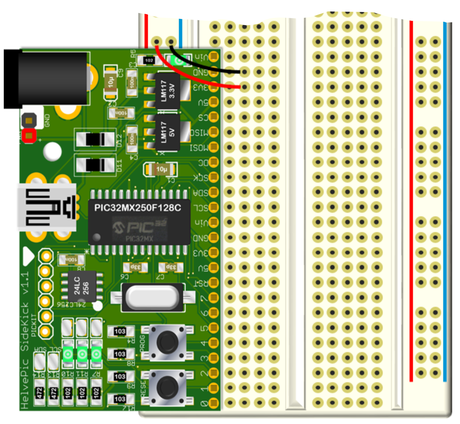
The Helepic32 BBside goes into the side of a breadboarde leaving allmost all pins of the breadboard available.
This page will take you through the board design and some examples
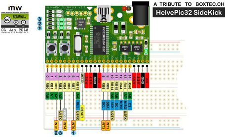
The pinmap of the board.
From left to right:
- GPIO 0 - Analog A0
- GPIO 1 - Analog A1
- GPIO 2 - Analog A2 - Interrupt I2
- GPIO 3 - Analog A3 - Uart1 TX
- GPIO 4 - Program - Interrupt I4
- GPIO 5
- GPIO 6 - Interrupt I0
- GPIO 7 - Analog A4 - SPI_Reset - Uart1 RX
- Reset and Power Pins
- I2C SCL
- I2C SDA
- SPI SCK
- SPI D/C
- SPI MOSI
- SPI MISO
- SPI CS
- Power pins
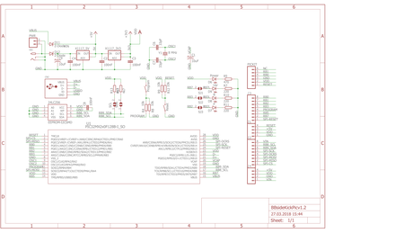
The board design is derived directly from the previous HelvePic32 boards.

The core is the PIC32MX250F128B porcessore in SMD, the crystal with its capacitors, a tantal capacitor for the Vcap pin and the two buttons to reset and to program the board.
The board can is connected to your PC via the USB port, used for communication and power.
The board goes into bootloader when you press and hold the program button while you press reset. With the two buttons next to each other, this can be done with one finger.
The 6 pins left of the USB port can be used with PicKit 3 to program the chip directly or flash a new bootloader.
The board can be powered through a barrel jack (2.1mm) or via two pins.
The highlighted section shows the two voltage regulators both capable to run at 800 mA. The input voltage should not exceed 12 Volts

The board has three on-board LED to play with.
The LED will also indicate bootloader mode with one flashing rapidly.
The two resistors above the LED are pull-up resistors for the I2C bus.
All LED and the pull-ups can be deactivated by de-soldering the bridges
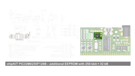
Optionally, there is a EEPROM on the board that can be adressed via I2C
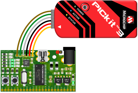
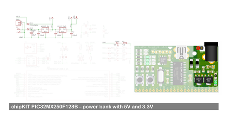
The board can be flashed with teh PicKit 3 (or 4) usinf the MPLAB IDE from MicroChip.
The board comes with the chipkit bootloader and threfore does not require the PicKit3 for programming.
If you flash the chip with your own bootloader, it is recommended to read and save the original bootloader.

Video showing how to solder this SMD board by hand
Video showith the speed of the board by running the OLED demo from Henning Karlsen