
Encoder LED Ring (Mayhew Labs)

This ring encoder is a nice breakout to learn how to use a shift register and to read an encoder using interrupts.
It comes without the encoder in the center so make sure you order one with it. There are encoders with a switch when pressed and this is supported by the breakout.
The breakout is operational with 5V as well as 3.3V
Shift register
Shift registers are very common in the world of chipKit and Arduino. They allow to store data in one or more register and only block a few pins on the micro controller. Register can be chained so that one output line can feed multiple registers.
In a register, each bit of the data represents the state of an output pin. A commonly used shift register is the 74HC595, which has 8 output pins, so one byte of data controls these pins nicely. A b00000000 turns all pins to LOW, a b11111111 turns all pins to HIGH.
So the only remaining question is: how do I get the byte into the chip?
This is done sequentially, a method used on all serial communications. In this setup, there is a pin where we apply a clock signal. A clock signal is nothing else than a signal that goes from HIGH to LOW and back with a steady period. Usually, when the signal goes from LOW to HIGH (rising), the attached chip does something, in our case, it reads state of the data pin. Some chips act on a falling condition, but that does not change the idea. So when the clock ticks, the shift register sets the state found at the data pin to the first bit in its register and shifts all bits in the register one bit higher. So the byte needs to be shifted in with the highest bit first which is called MSB (Most Significant Bit).
And what happens to the highest bit? It gets lost - that simple. However, it is shifted to an overflow pin which can be read by a chained register so that the bits overflows into the next register. There is not limit on how many registers you may chain.
In the code-base of chipKit there is a routine that does this standard task: shiftOut( data-pin, clock-pin, mode, data-byte) where mode is MSBFIRST (in our case) or LSBFIRST.
TLC925
On the ring encoder breakout, Mayhew Labs use a TLC925 register. This differs from the 74HC595 only by the number of output pins, being 16 instead of 8. This means that we need to shift two bytes into the register. The code looks rather simple:
void shiftOut16(uint16_t data)
{
        byte datamsb;
        byte datalsb;

        datamsb = (data&0xFF00)>>8;  // mask out the MSB and shift it right 8 bits
        datalsb = data & 0xFF;  // Mask out the LSB

        digitalWrite(latchPin, LOW);  // first send latch low
        shiftOut(datPin, clkPin, MSBFIRST, datamsb);
        shiftOut(datPin, clkPin, MSBFIRST, datalsb);
        digitalWrite(latchPin, HIGH);  // send latch high to indicate data is done sending
}
We first split the 16 bit word into two bytes. Then we take the latchPin LOW, shift the two bytes in the right order and take the latchPin HIGH again.
latchPin? This is a nice feature of most shift registers: they have a pin that tells the register to hold the current state of the output as it is while the latch is LOW. SO I can shift the new information into the register without changing directly the output state. When I put the latch back to HIGH, all register output pins go to the new loaded state at once avoiding any flickering.
Wiring the Shift Register

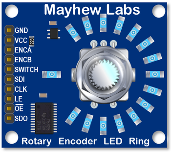
Looking at the breakout we find that there are pins with the following labels:
- GND - connect this to Ground
- VCC - connect this to Vcc (either 3.3V or 5V will work as the chip is 5V tolerant)
- ENCA - encoder pin A (we check this later)
- ENCB - encoder pin B (we check this later)
- SWITCH - the momentary switch pin of the encoder (we check this later)
- SDI - Serial Data In
- CLK - Clock
- LE - Latch
- OE - Output Enable (there is a bar above the OE)
- SDO - Serial Data Out
So SDI is our data pin, CLK is where we will put our clock signal and LE is the latch pin. The OE pin (with the bar above) is an additional pin of the TLC925 to switch on or off the entire output pins. Keeping this one HIGH will leave the Leds offline, so we connect that one to GND.
The Encoder
An encoder is a nice little device: It has two output pins that toggle from LOW to HIGH and back whenever the encoder is rotated. The two pins however are slightly shifted by half a pulse width so that in the event that one line changes the state, the other line indicates if we are turning forward or backward. So all we need to do to read out an encoder is to check one of the pins to go up and then test the state of the other line to determine if we moved froward or backward. But we have got better things to do with our micro-controller than to sit and wait for the encoder to turn. But if we do other things we might miss the encoder changing its state.
For the handling of such unpredictable events that interrupt our normal program execution, the micro-controllers have interrupt pins (Arduino:2 - chipKit:5). You can attach a routine to such an interrupt and once the state changes, the routine gets called while the program itself is halted. The Arduino reacts to the event RISING, FALLING and CHANGE, whereas the chipKit only reacts to RISING and FALLING.
Similar to the encoder pins, we can attach the switch to another interrupt pin to handle the unpredictable switching. With the information above, we can wire the entire breakout to the micro-controller and use the following code to let a Led rotate according to the encoder being turned. If the switch is pressed, all lights go on until the encoder is turned again. At the beginning, half the Leds are lit to show that the breakout is working.
The variables used in the interrupt routines must be declared volatile so that the controller can handle them correctly.
Code Example
#include <HelvePic32.h>

#define spin nP[RIGHT][3]

volatile int encoderPin1 = nP[RIGHT][4];        // pin connected to INT-1 by default
volatile int encoderPin2 = nP[RIGHT][5];
volatile int number = 0;
volatile boolean swPressed = false;
// used in loop and both interrupt routines
int oldnumber = number;
#define latchPin nP[RIGHT][0]  // Shift registers' rclk pin
#define clkPin   nP[RIGHT][1]  // Shift registers' srclk pin
#define datPin   nP[RIGHT][2]  // shift registers' SER pin

void setup(){
        pinMode(latchPin, OUTPUT);
        pinMode(clkPin, OUTPUT);
        pinMode(datPin, OUTPUT);
        digitalWrite(latchPin, LOW);
        digitalWrite(clkPin, LOW);
        digitalWrite(datPin, LOW);

        pinMode(encoderPin1, INPUT);
        digitalWrite(encoderPin1, HIGH);
        pinMode(encoderPin2, INPUT);
        digitalWrite(encoderPin2, HIGH);
        attachInterrupt(1, isr_A, FALLING);
        attachInterrupt(3, isr_SW, FALLING);

        shiftOut16(0x00FF);
}

void loop(){
        uint16_t val;

        if (oldnumber != number){
                oldnumber = number;
                LedSingle((uint16_t)number);
        }
        if (swPressed) {
                shiftOut16(0xFFFF);
                swPressed = false;
        }
}

void isr_A(){
        delay(3);                                                               // Debounce time
        // Trade off bounce vs missed counts
        int LSB = digitalRead(encoderPin1);
        int MSB = digitalRead(encoderPin2);

        if(LSB == LOW){                                                 // A still LOW ?
                if(MSB == HIGH) number++;
                if(MSB == LOW)  number--;
        }
}

void isr_SW(){                              // SW went LOW
        swPressed = true;
}

void LedSingle(int pos) {
        int lpos;
        uint16_t lout;

        lpos = pos % 16;
        lout = 1 << lpos;
        shiftOut16(lout);
}

void shiftOut16(uint16_t data)
{
        byte datamsb;
        byte datalsb;

        datamsb = (data&0xFF00)>>8;  // mask out the MSB and shift it right 8 bits
        datalsb = data & 0xFF;  // Mask out the LSB

        digitalWrite(latchPin, LOW);  // first send latch low
        shiftOut(datPin, clkPin, MSBFIRST, datamsb);
        shiftOut(datPin, clkPin, MSBFIRST, datalsb);
        digitalWrite(latchPin, HIGH);  // send latch high to indicate data is done sending
}